| |
 |
Aquaticus ROV | |
|
| |
Homebuilt underwater robot | Research |
|
Basic specificationI would like to explore rather deep and cold places (see Exploration section). The temperature of the water in Baltic Sea is 1–22°C . Interesting wrecks are at 50–80m. I assume that the robot should work in the following enviroment:
Maximum depth: 100m I guess the main problem will be the pressure (10bar) at 100m. EquipmentVisionA camera is necressary and source of light. I'm considering using 2 cameras for stereovision. It is possible to see a real 3D pictures using special glasses. I plan to buy simple a CCD camera and 2x50W/12V halogen lamps.ProbesA compass, temperature and pressure sensor. Maybe a moisure sensor to warn when the robot leaks.ThrustersMinimalistic design using only 3 electric engines.ManipulatorSimple open–close manipulator. Similar to one that Seabotix use or at Homebuilt rov's (Misc. Projects).ControlATMEL ATmega8 processor inside the robot, controlled via an RS-485 from a laptop + joystick (later control console). AVR processorsGeneral descriptionI will focus on ATMega8 micro controller, but the description is valid for other AVR micro controllers as well. AVR is a family of 8-bit micro controllers. They're based on RISC core, it means: most instructions are executed in one clock cycle, large number of general registers, most operations can have any register(s) as arguments. They integrate FLASH memory for program storage, SRAM memory, and non volatile EEPROM. Below is a list with some informations:
Here are listed peripherals integrated in the micro controller:
ISPISP is abbreviation of In-System Programmable, ATMega has additional feature – In-System Self-Programmable it simply means that the FLASH (and EEPROM) memory can be programmed without desoldering or ejecting the chip from the socket. During design you must remember to add 10 pins connector and make proper connection with ATMega8. If the AVR is not set for use with internal RC oscillator you have to attach some clock source (the one for which the microcontroller if configured for - for example crystal oscillator). Clock source can be configured using fuse bits, which are set up during the MCU programming. There's also other possibility - the micro controller can program itself using (programmed earlier) boot code – code can be downloaded ex. through serial port or two wire interface (I2C). Design guidelinesSimply add this connector to your design: 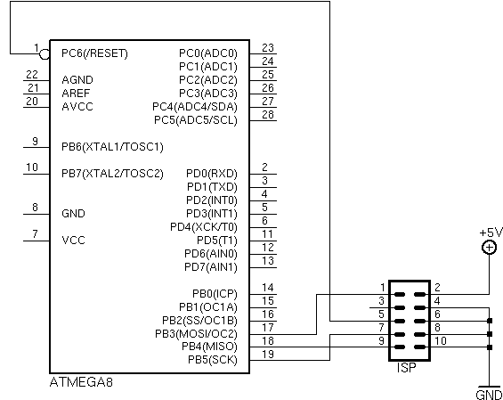
Below is a closer look on the connector (sometimes known as IDC10 or ML10), it's stk200 starter kit compatible. You can use any other connector, just remember about all signal wires (RESET, CLK and so on) and the plug which must be the same as in your programmer. There are number of plug "standards" which can be found on Internet, I think that stk200 is the best choice because it's the same as in Atmel starter kit and many programmers support it. 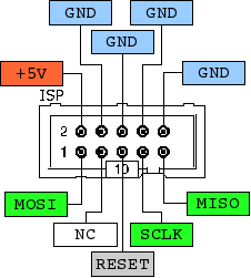
The third pin is described as NC (not connected), but you can connect a LED (on the AVR side) to indicate programming process. The ISP interface can coexist with devices attached to the same MCU port lines, as long as they're used as outputs, not inputs. Imagine, if an external device pulls down one of the signals, the ISP interface won't work. You can also make use of bootloader code, which you must write on your own, or use a precompiled one. In that case you don't need to have the ISP interface on your PCB, but remember - the MCU must have some external interface (serial, I2C) to download the code, additionaly you need to program the bootloader code first. Good: save some space on PCB, free up some port pins, no need to have a direct access to the board - MCU firmware updates can be made externally; bad: can be slower, bootloader takes up some FLASH space, you must write a bootloader. Programmer deviceWhat's great about ISP is that you don't need sophisticated programmer. I will describe here a simple LPT (parallel port) programmer. There are simpler designs (just wires), but I recommend this one – TTL 74HC244 will protect the parallel port from being damaged. Here's a schematics (based on schematics on PonyProg site): 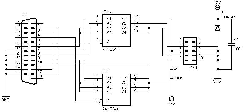
If you use SMD parts the programmer will fit in DB-25 casing. To program the device connect the programmer with your PCB one to one cable. To program you need some tools, read below. ToolsAnother important issue with AVR processors is that there are a lot of free tools available. I'll list them here with short description:
More helpIt's always hard to start, if you get familiar with the AVR
architecture everything be easy. The "bad" thing about AVRs is that, on the
beginning, it's hard to learn all the quirks with different issues (like
programming) – the CPU is highly configurable, it makes it more flexible
but harder to learn. That's my opinion of course. Below are some links
where you can find tutorials and where you can ask for help. The knowledge base
for you is AVR data sheet, it's a bit technical, but has a lot of examples (in
assembler and C) how to use AVR peripherals. You can find data sheets on Atmel
site.
There is also one more possibility. If you do not like C or assembler, you can use BASIC. There is a commercial product BASCOM – perfect for small projects. Has many high level functions and is very easy to use. You can compile up to 2kb of code for free. If you have a problem don't hesitate to ask. CameraVideo signal
Most cameras have a standard composite video output signal (described as 1Vpp 75 Ohm).
You can directly connect camera output to the TV or a video recorder. This is
the best choice, cheap and widely used. Because it uses an analog
signal, you need an extra equipment to connect it to a computer, but
in most cases it is not necessary – you can use standard video
monitor. Video to USB converter costs about
50&euro
, TV or video PCI cards
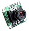
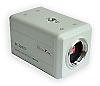
are even cheaper. There are other solutions, like firewire or even RS-232. I see no any reason to use firewire, maybe if you want to use video camera with firewire input as monitor. I expect only problems when using firewire, especially with maximum length of the connection cable. One (and the only) good thing about an RS-232 camera is that you can plug it directly to the computer. The very bad is that it can provide only 3 frames per second! This is right solution if you like to watch static images. PowerMany cameras are powered by 12V, some 5V. Consumer video cameras (VHS, DV, Hi8) needs the same voltage as its batteries, e.g. 7.2V. If your robot is powered by 12V try to choose 12V camera. For other voltages you need voltage converter. ResolutionResolution of CCTV cameras is defined by number of lines (TVL). More lines means more details on the screen. Typical values are from 320 to 470 lines. There are cameras with 600 lines but use it only if you have unlimited budget. LensA very important part of the camera. For most CCTV cameras you need to buy lens separately. Parameters of lens worth to mention:
Sensor
There are two types of sensors: CCD and CMOS. All cheap cameras have
CMOS sensor. More expensive and consumer video cameras have CCD
sensor. Most important parameter of sensor is sensitivity. This is
minimum amount of light that camera needs to proper work. Less number
means better parameter. 0.1lux very good, 1lux average, 3lux
rather bad. Note that some cameras have Sensitivity 0lux. It means
they can work in infrared range and thus you need an extra infrared
lamp. Black and white sensors have usually better sensitivity then
color ones. What to chooseI bought an old second hand consumer camera with intention to adapt it as a primary vision for the robot. But final decision is not taken yet. Im considering 3 options.
CompassNavigation in the underwater environment is not as easy as on the ground. You have only images from a camera, no sun, no characteristic points, water is not as clear as the air. Expensive commercial vehicles uses sonar, but for homebuilt ROV an old fashioned compass is enough. There are two main solutions using:
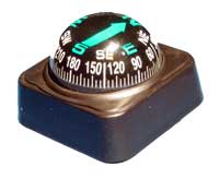
It is worth to mention that you must be careful installing a compass in the robot. It can be affected by electronic and electric engines. Analog compass
Use car compass (not "flat") with a ball. Similar to the one shown on the left. It costs about 3. For practical use, look at Subz NZ page. Digital compassDigital compass can be easily connected to micro controller. Very popular design use Dinsmore 1490 chip. Two combined units provides only 8 headings (N, NE, E, SE, S, SW, W, and NW). For more details look at Arrick Roboticks. If you need more accuracy you must use different chip. Here you have a list of popular ones:
For more links look at Brooke's Home Page.
If you do not want to build a digital compass from scratch, you can buy a compass module. It is PCB with one of the above chips.
Personally I would try to build the compass from scratch using Philips KMZ51. Here are some links to KMZ51 compasses: |
 The
idea is simple, you must attach classic compass to the robot in a way you can
see it in the camera. If your compass is not waterproof or can not handle high
pressure you can use little trick. Put the compass into camera housing and
attach a mirror in the front of camera (not in housing). You can see the compass
in the mirror using camera.
The
idea is simple, you must attach classic compass to the robot in a way you can
see it in the camera. If your compass is not waterproof or can not handle high
pressure you can use little trick. Put the compass into camera housing and
attach a mirror in the front of camera (not in housing). You can see the compass
in the mirror using camera.